Leading manufacturer of high precision optical parts
sales@tzjingda.com
+86 137 7570 5286(WeChat)
Leading manufacturer of high precision optical parts
sales@tzjingda.com
+86 137 7570 5286(WeChat)
Fast And Safe Logistics
Get samples for free
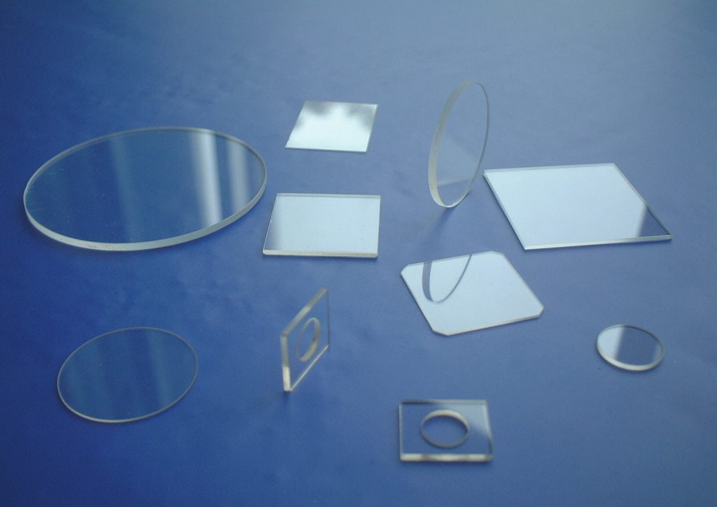
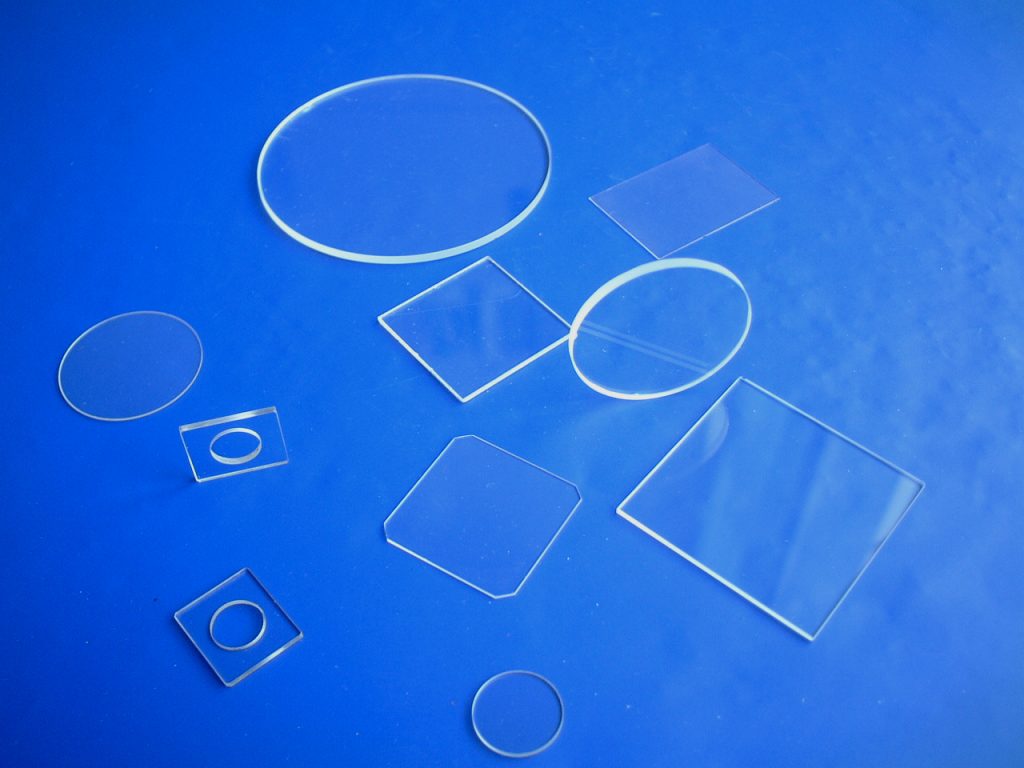
Waveplate (retardation plates or phase shifters) is made from birefringence material.
The velocities of the extraordinary and ordinary rays through the birefringent materials vary inversely with their refractive indices.
The difference in velocities gives rise to a phase difference when the two beams recombine.
At any specific wavelength the phase difference is governed by the thickness of the retarder.
Please specify the wavelength, phase retardation, dimension and type when you purchase it. Custom designed waveplate is available upon request.
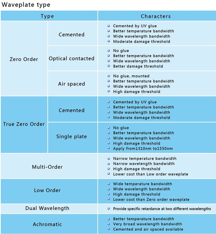
The thickness of a Half Waveplate is such that the phase difference as 1/2 wavelength (True-Zero Order) or some multiple of 1/2 wavelength (Multiple Order). When applying a linearly polarized beam to a Half Waveplate, it emerges as a linearly polarized beam.
The thickness of the Quarter Waveplate is such that the phase difference as 1/4 wacelength (True-Zero Order) or some multiple of 1/4 wavelength (Multiple Order). When the angle between incident beam’s polarization plane and waveplate’s optical axis become 45 deg, a linearly polarized incident beam comes out as circularly polarized while a circularly polarized incident beam comes out as linearly polarized.
In order to analyze the effective bandwidth of waveplate, we make the following spectrum system test in lab.
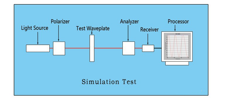
In application, when linearly polarized light pass through one waveplate, the outgoing light will be elliptically polarized. The factors which affect the axis length of outgoing beam are: polarization situation of incident light (polarizer’s T/R extinction ratio), precision of waveplate, fast axis orientation of waveplate, temperature of wavplate and etc. And the factors which affect the waveplate precision are: orientation precision of crystal axis, thickness of waveplate, parallelism of waveplate, purity of waveplate. If we set the length of long axis as P while short axis as S, we can consider the incident polarized light as P=1, S=0. Then theoretically, the outgoing light will be P=0, S=1 through a half waveplate and P=1, S=1 through a quarter waveplate.
Take the half waveplate with 632.8nm wavelength for example, if we put the analyzer and polarizer in parallel, then theoretically the weakest intensity spot should show at 632.8nm on processor. The error between weakest intensity spot’s wavelength and 632.8nm is exactly the error of the waveplate (the system error can be less then 0.3nm after adjustment).
The ratio between system’s maximum light intensity and certain wavelength’s light intensity is called this certain wavelength’s light ratio. Take light ratio>500:1 of 1/2 Zero Order Waveplate and light ratio=1:1±1/250 of 1/4 Zero Order Waveplate as reference, we can get the theoretical effective bandwidth (actual effective bandwidth is smaller than theoretical).
Zero Order Waveplate 1/2@266nm & 1/4@266nm:
1/2@266nm effective bandwidth ±5nm(Half bandwidth 5nm, full bandwidth 10nm).
1/4@266nm effective bandwidth ±1nm.
Zero Order Waveplate 1/2@532nm &1/4@532nm:
1/2@532nm effective bandwidth±13nm.
1/4@532nm effective bandwidth±2.4nm.
Zero Order Waveplate 1/2@1064nm &1/4@1064nm:
1/2@1064nm effective bandwidth ±28nm.
1/4@1064nm effective bandwidth ±5nm.
Zero Order Waveplate 1/2@1550nm &1/4@1550nm:
1/2@1550nm effective bandwidth ±40nm.
1/4@1550nm effective bandwidth ±7nm.
Below Picture shows the different bandwidth of 1/2@632.8nm waveplate of Multi Order/ Low Order/ Zero Order.
| Material: | Crystal Quartz |
| Dimension: | As requirement |
| Phase Retardation: | λ/8, λ/4, λ/2 or discretional |
| Wavefront Distortion: | ≤λ/10@632.8nm (except UV cemented waveplate) |
| Retardation Tolerance: | ≤λ/300, ≤λ/500 |
| Wavelength Tolerance: | 260-1600 nm |
| Parallelism: | ≤2″ (except UV cemented waveplate) |
| Surface Quality: | 20/10, 40/20 scratch and dig |
| Clear Aperture: | ≥90% |
If you are interested in any of our products or would like to discuss a customized order, Please feel free to contact us.